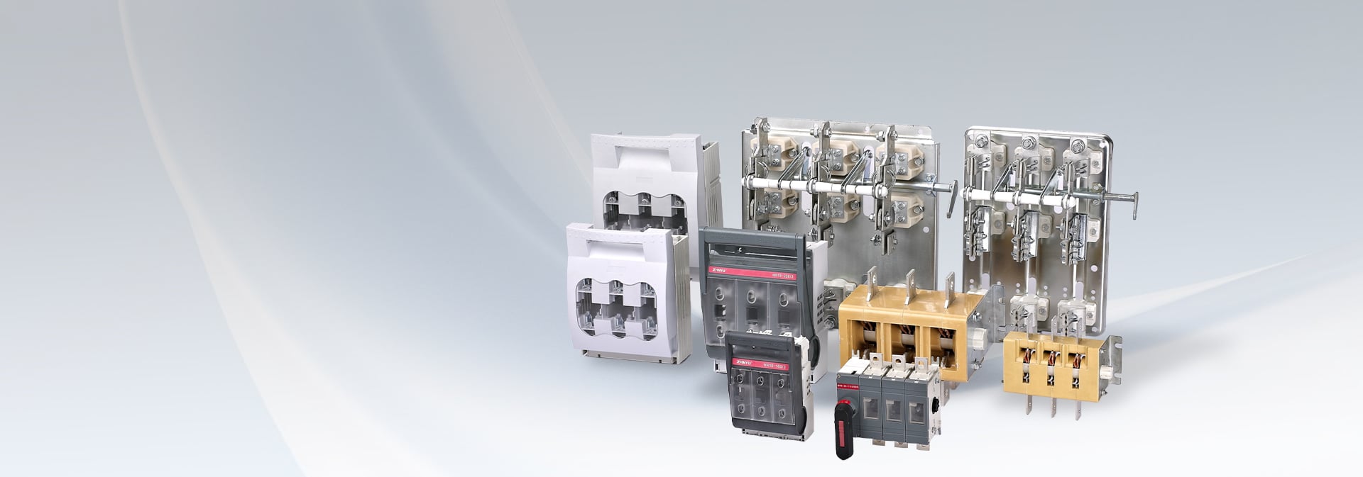
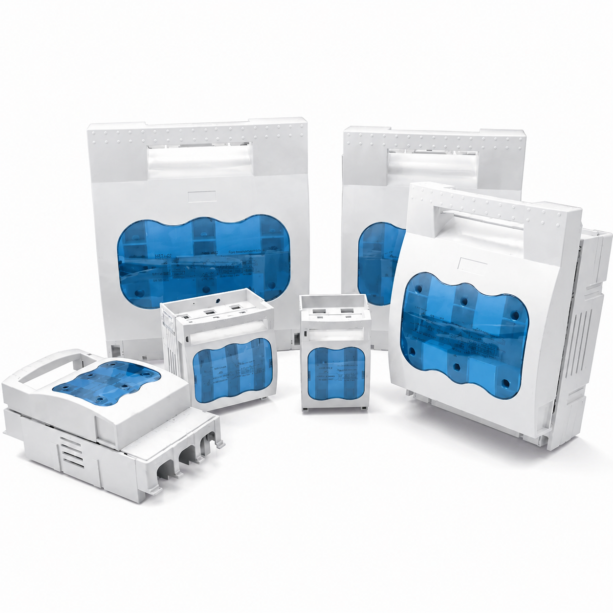
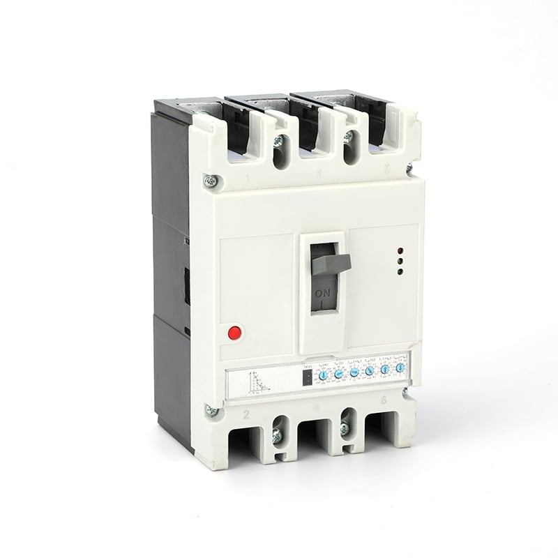
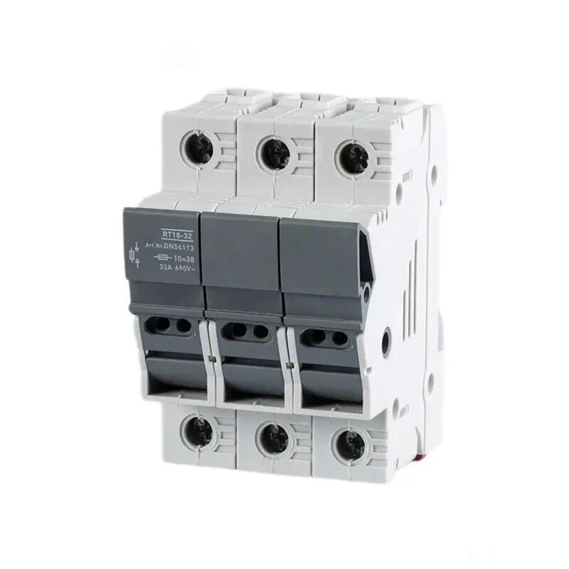


HR17 series fusible isolation switch is a new product developed by our company. Its rated insulation voltage is 800V, rated working voltage to 690V,
rated working current to 630A, rated frequency is 50Hz, suitable for distribution circuit and motor circuit with high short circuit current, used as a
power switch, isolation switch and emergency switch, and for circuit protection, but generally not as a direct opening and closing of a single motor.
Standards: GB14048.3, IEC 60947-3.
Application Scenarios
The HR17 Series Fuse Switch Disconnector is designed for low-voltage power distribution systems and combines the functions of circuit isolation, load switching and short-circuit protection through fuse links. It is widely used in industrial, commercial and infrastructure electrical installations where reliable isolation and protection are required.
Industrial Power Distribution
Widely used in manufacturing plants, workshops, machinery systems and industrial control panels as a main switch or branch circuit protection device. It provides safe isolation during equipment maintenance and protects circuits against overload and short-circuit faults when used with appropriate fuse links.
Commercial Buildings
Suitable for shopping malls, office buildings, hotels, hospitals and commercial complexes, ensuring reliable power distribution and safe disconnection of electrical circuits.
Motor Control and Distribution Cabinets
Commonly installed in motor control centers (MCC), switchboards and distribution cabinets as an incoming or outgoing feeder switch, providing visible isolation and dependable protection.
Renewable Energy Systems
Used in photovoltaic combiner boxes, energy storage systems and other renewable energy installations where circuit isolation and overcurrent protection are required.
Utility and Infrastructure Projects
Applicable to power substations, telecommunications facilities, water treatment plants, transportation systems and municipal projects requiring dependable switching and isolation functions.
Marine and Special Applications
Its compact structure, reliable contact system and high operational safety make it suitable for shipbuilding, offshore platforms and other demanding electrical environments.
Normal working conditions
The ambient air temperature is not higher than +40℃, not lower than -5℃;
The elevation of the installation site shall not exceed 2000m;
When the maximum temperature is +40℃, the relative humidity of the air does not exceed 50%, and a higher relative humidity can be allowed
at a lower temperature. Special measures should be taken for condensation occasionally caused by temperature changes;
The pollution level of the surrounding environment is level 3;
The switch should be installed in a place where there is no significant shaking, shock vibration and no rain or snow attack. At the same time, the
installation site should be free from explosive dangerous media, and the media should be free of gas and dust enough to corrode metal and
destroy insulation.
Structural features
The HR17 Series Fuse Switch Disconnector adopts a modular and compact design, integrating a switch mechanism and fuse protection into a single unit. It provides reliable switching performance, visible isolation and high short-circuit protection capability.
Integrated Fuse Protection
The switch is designed to accommodate NH/NT type fuse links, allowing the fuse to provide effective short-circuit protection while the switch mechanism ensures safe operation and isolation.
Visible Isolation Gap
When the switch is opened, a clear visible isolation distance is created, allowing maintenance personnel to verify the disconnected state and improving operational safety.
High Mechanical Strength
The housing and operating mechanism are manufactured from high-quality insulating and flame-retardant materials, providing excellent mechanical durability and electrical insulation performance.
Reliable Contact System
Silver-alloy contacts and optimized contact pressure ensure low contact resistance, reduced temperature rise and stable current-carrying performance.
Fast Switching Mechanism
The quick-make and quick-break operating mechanism enables rapid switching action, reducing arcing time and improving electrical endurance.
Modular Installation Design
The product supports panel mounting and cabinet installation, making it suitable for various low-voltage switchgear and distribution equipment configurations.
Safe and Convenient Operation
The handle mechanism is designed for easy manual operation and can be equipped with padlocking devices to prevent unauthorized operation during maintenance.
Excellent Arc Suppression Performance
The optimized contact structure and fuse coordination effectively limit fault currents and reduce damage to downstream equipment.
Product Model and Its Meaning Technical Parameters
Conventional eating urent(A)
63(32)
160(100)
250
400
630
Rated insulation votage(V)
800
Rated working curent (A)
400V AC21
32、63
100、160
250
400
630
400V AC22
32、63
100、160
250
400
630
400V AC23
一
100、160
250
400
630
690V AC21
一
100、160
250
400
630
690V AC22
一
100
160
315
425
Operating force N
≤120
≤250
≤350
≤350
≤450
Fuse
Model
RT19-125
NT00、RT16-00
NT1、RT16-1
NT2、RT16-2
NT3、RT16-3
Melt at 400V Rated curentA (Rated imited short icuit curent)
20 32 63
20、25、32、35、40、50、63、80、100、125、160 (≥100kA)
80、100、125、160、200、224、250 (≥100kA)
125、160、200、224、250、300、315、355、400 (≥100kA)
315、355、400、425、500、630 (≥100kA)
Melt at 690V Rated curent A (Rated limited short icuit curent)
—
20、25、32、35、40、50、63、80、100 ≥50kA
80、100、125、160、200 ≥50kA
125、160、200、224、250、300、315 ≥50kA
315、355、400、425 ≥50kA
External appearance and installation dimensions HR17 series (fixed)switch mounting dimensions
Scope of Application
Application Scenarios
Normal working conditions
Structural features
Product Model and Its Meaning
Technical Parameters
Conventional eating urent(A)
63(32)
160(100)
250
400
630
Rated insulation votage(V)
800
Rated
working
curent
(A)
400V
AC21
32、63
100、160
250
400
630
400V
AC22
32、63
100、160
250
400
630
400V
AC23
一
100、160
250
400
630
690V
AC21
一
100、160
250
400
630
690V
AC22
一
100
160
315
425
Operating force N
≤120
≤250
≤350
≤350
≤450
Fuse
Model
RT19-125
NT00、RT16-00
NT1、RT16-1
NT2、RT16-2
NT3、RT16-3
Melt at 400V
Rated curentA
(Rated imited
short icuit curent)
20
32
63
20、25、32、35、40、50、63、80、100、125、160
(≥100kA)
80、100、125、160、200、224、250
(≥100kA)
125、160、200、224、250、300、315、355、400
(≥100kA)
315、355、400、425、500、630
(≥100kA)
Melt at 690V
Rated curent A
(Rated limited short icuit curent)
—
20、25、32、35、40、50、63、80、100
≥50kA
80、100、125、160、200
≥50kA
125、160、200、224、250、300、315
≥50kA
315、355、400、425
≥50kA
External appearance and installation dimensions
HR17 series (fixed)switch mounting dimensions
On-off type
Overall imension(mm)
Mounting size(mm)
Terminal size
A
B
C
D
E
a
b
φC
M
HR17B-40
2/
55
116
76
150
21
25
φ6
/
/
3/
76
116
76
150
21
42
/
φ6
HR17B-63
2/
74
116
76
150
31
35
/
φ6
/
/
3/
105
116
76
150
31
62
/
φ6
HR17B-160
2/
75
200
83
205
33
43
25
φ7
2×20
M8
3/
106
200
83
205
33
66
25
φ7
4/
138
200
83
205
33
100
25
φ7
HR17B-250
2/
128
247
110
295
57
72
50
φ11
2×30
M10
3/
185
247
110
295
57
114
50
φ11
4/
242
247
110
295
57
172
50
φ11
HR17B-400
2/
145
290
125
340
65
80
50
φ11
2.5×33
M10
3/
210
290
125
340
65
130
50
φ11
4/
276
290
125
340
65
195
50
φ11
HR17B-630
2/
175
300
145
360
81
90
50
φ11
3.5×40
M12
3/
256
300
145
360
81
162
50
φ11
4/
340
300
145
360
81
243
50
φ11
HR17 Series (Mount)switch mounting dimensions
On-offtpe
A
B
C
D
E
F
H
HR17B-160/30J
106
200
97
60
33
87
200
HR17B-250/30J
185
247
128
88
57
110
220
HR17B-400/30J
210
290
145
97
65
125
268
HR17B-630/30J
256
300
160
112
81
139
285