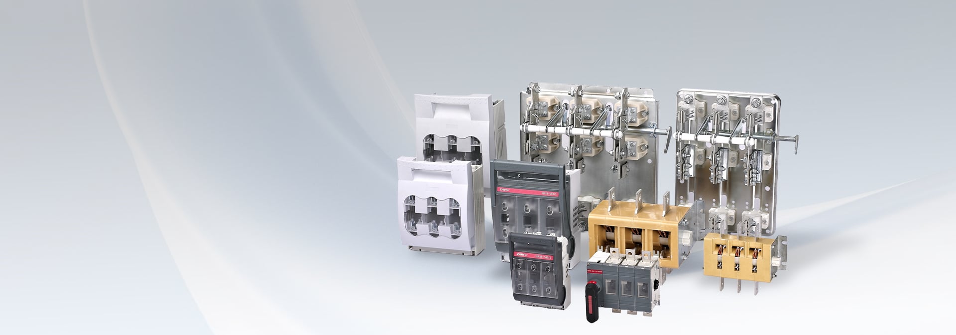
HD/HS Series Open-Type Knife Switches Manufacturer

All Categories
HD/HS Series Open-Type Knife Switches Manufacturer

Isolator

Home >  Products >  Isolator

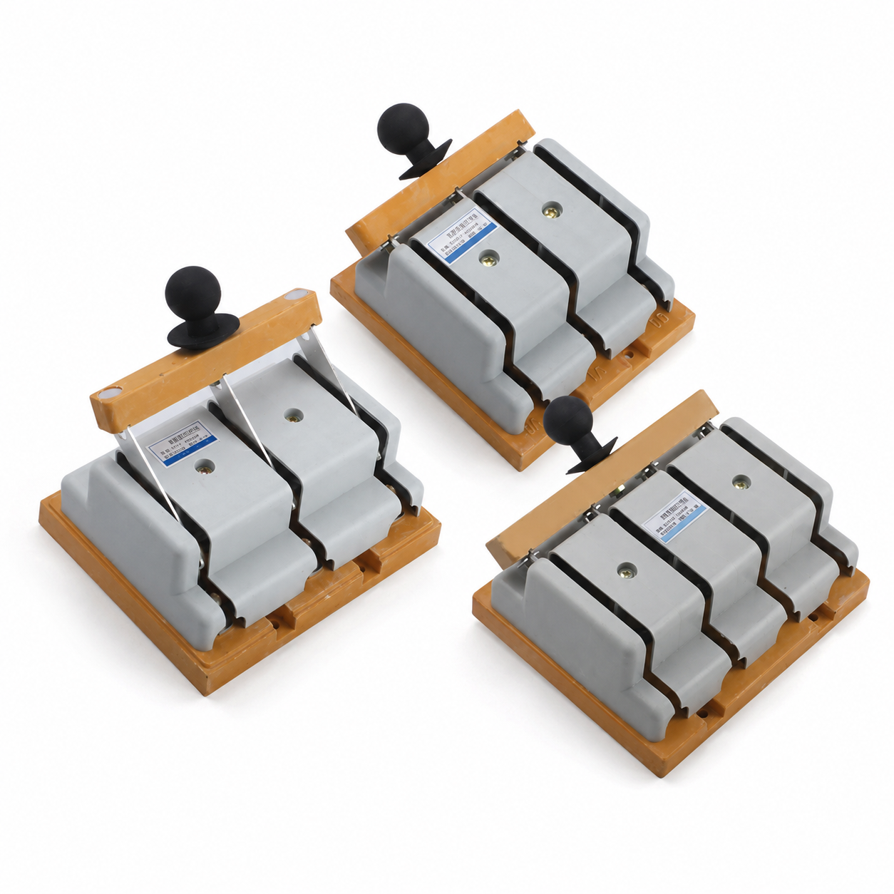
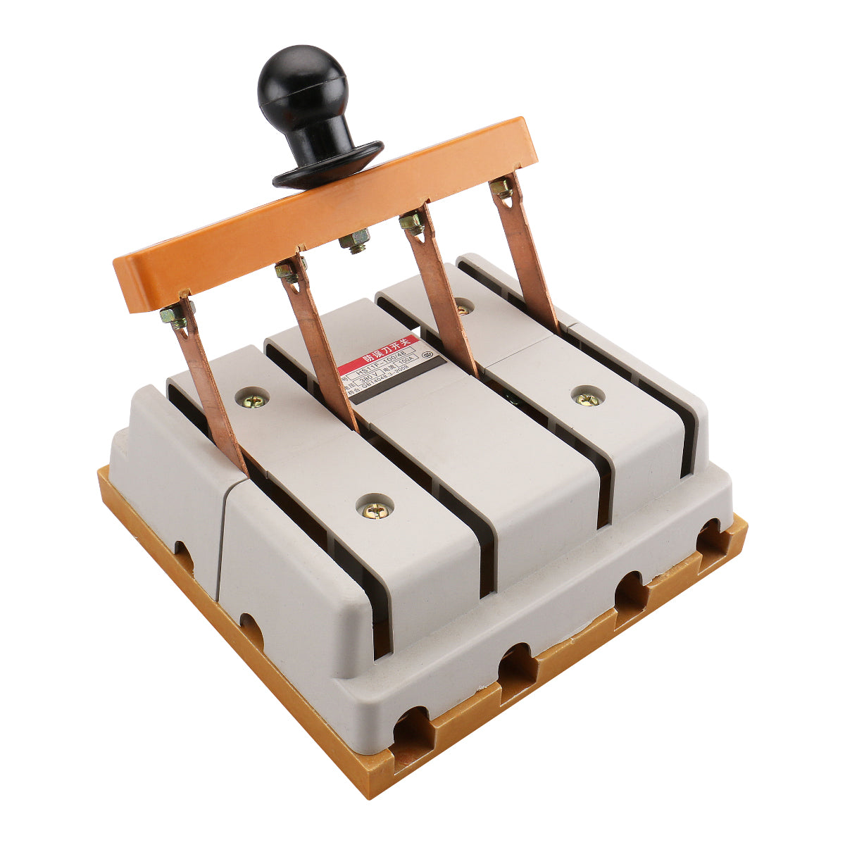
HD and HS series open-type knife switches

Switches without an arc extinction chamber must not be operated under load; switches equipped with an arc extinction chamber can interrupt the corresponding rated current. 

Appurtenance:

Description

warn
1. Switches without an arc extinction chamber must not be operated under load; switches equipped with an arc extinction chamber can interrupt the corresponding rated current. If a switch without an arc extinction chamber is used to interrupt the rated current, the absence of an arc extinction device makes arc generation during interruption unavoidable, posing significant risks such as electric burns, fires, or short circuits. For knife switches with an arc extinction chamber operating at the rated current level, operation with wet hands is strictly prohibited to prevent electric shock accidents.
2. Products with misaligned contacts shall not be put into use; due to incorrect contact positioning, the contact surface of the cutting blade fails to meet specified requirements. Forced operation may cause a sharp rise in contact temperature, posing risks such as fire hazards.

pay attention to
1. The installation site of the knife switch shall be free from explosion hazards and corrosive gases, with attention paid to moisture protection, dust prevention, and vibration resistance.
2. Insulation Testing
This switch has undergone insulation testing in accordance with standard specifications before leaving the factory. If retesting is required prior to installation, it must follow the steps below:
a) Measure the insulation resistance at temperatures ranging from –5°C to +40°C;
b) Use a 1000 V megohmmeter;
c) Location of power-frequency voltage application; when the main contacts are in the closed position:
1) Between the connections of all pole components and the grounding point on the switch base plate;
2) Between each pole and its adjacent pole.
When the main contact is in the open position:
1) Between all charged parts of the connected poles and the grounding terminal plate of the switch;
2) Between the connections of each pole at the input end and those connected to each level at the output end.
3) No insulation breakdown or flashover shall occur during the test (leakage current shall not exceed 100 mA).
4) The insulation resistance shall not be less than 10 megohms.

1 Scope of Application
The HD open-type knife switch and HS knife-shaped transfer switch (hereinafter referred to as knife switches) have a rated operating frequency of 50Hz, a rated operating voltage of 400V AC, and a rated current up to 3000A. They are used in power distribution equipment in industrial enterprises to connect or disconnect AC circuits with rated currents or serve as isolating switches (for use in DC circuits, consultation with the manufacturer is required). Details are as follows:
1.1 The HD (HS) 11 central handle-type switch is primarily used in power stations; it should not be employed to disconnect live circuits and is intended solely for electrical isolation purposes.
1.2 The HD (HS) 12-side lateral front lever-operated switch is primarily used in switchgear designed for front operation and front maintenance, with the operating mechanism installable on either side of the cabinet.
1.3 The HD (HS) 13 central front-lever operating mechanism switch is primarily used in switchgear units designed for front operation with rear maintenance access, featuring the operating mechanism mounted directly at the front.
1.4 The HD (HS) 14 features a side-mounted handle-type switch, primarily installed in the power box.
1.5 Switches equipped with arc suppression chambers can interrupt appropriate current loads; other series of knife switches are intended solely for isolation purposes.
Product compliance standard: GB/T 14048.3

2 Normal Working Conditions
2.1 Ambient air temperature: -5°C to +40°C, with an average value within 24 hours not exceeding +35°C;
2.2 Installation Site Altitude: No more than 2000 m;
2.3 Atmospheric Conditions: The relative humidity of the atmosphere shall not exceed 50% at an ambient air temperature of +40°C; higher relative humidity may be permitted at lower temperatures—for example, 90% at 20°C. Special measures must be taken to eliminate condensation that may form on product surfaces due to temperature fluctuations.
2.4 Pollution Level: Level 3;
2.5 Installation Category: Class III or Class IV;
2.6 Installation Requirements: The device shall be installed vertically in a location free from significant shaking, impact vibrations, or exposure to rain/snow. The installation site must also be free of hazardous explosive media and contain no gases or dust particles capable of corroding metals or damaging insulation.

3 Structural Characteristics
3.1 Except for the handle-type knife switch, all other knife switches of different specifications employ transmission mechanisms—lever-operated or rotating-operated mechanisms—with clear open/closed indication markers and reliable positioning devices. Additionally, arc-extinguishing enclosures fabricated by riveting insulating cardboard to steel grid plates are used to ensure safe and reliable circuit interruption.
3.2 Blade switches with ratings from 100 A to 400 A feature a single blade, whereas those above 600 A employ a double-blade design. Contact pressure is maintained by dual leaf springs on both sides. All contacts between the blades and external conductors are tin-plated to enhance surface protection and reduce contact resistance.
3.3 The mounting plate for the knife switch is made of flame-retardant phenolic glass fiber plastic through molding, offering excellent pressure resistance, arc withstand capability, and mechanical strength.

4 Type and Its Meaning

HD and HS series open-type knife switches details

5 Main Technical Parameters and Performance
The main technical specifications of the switchgear are shown in Table 1.
Table 1

Rated operating voltage (V)

Rated insulation voltage (V)

Agreed heating current (A)

Rated short-time withstand current (kA)

Rated impact withstand voltage (kV)

Electric Life (times)

Mechanical Life (times)

Operating Force (N)


400


690

100

6


8

500

5000

≤300

200

10

500

5000

≤300

400

20

300

5000

≤400

600

25

300

2000

≤400

1000

30

300

2000

≤450

1500

40

200

2000

≤450

2000

40

200

1000

≤450

3000

60

200

1000

≤450


6 Appearance and Installation Dimensions
6.1 The appearance and installation dimensions of the HD11 central handle-type front panel wiring knife switch are shown in Figure 1 and Table 2.
Table1
image.png
Table2

model

specifications

100A (Insulating Board)

200A

400A

600A

2P

3P

1P

2P

3P

4P

1P

2P

3P

4P adhesive board

1P

2P

3P

4P


HD11

A

140

140

120

150

190

260

50

190

210

300

160

240

260

360

B

210

210

210

210

210

210

270

270

270

270

340

340

340

340

C

50

50

60

70

70

140

80

160

80

160

100

200

100

200

D

140

140

140

140

140

140

190

190

190

190

140

140

140

140

E

50

50

-

70

70

70

-

80

80

80

-

100

100

100

F

160

160

160

160

160

160

215

215

215

215

274

274

274

274

H

215

215

220

220

220

220

270

270

270

270

330

330

330

330

h

105

105

115

115

115

115

135

135

135

135

130

130

130

130

J

105

105

110

110

110

110

146

146

146

146

240

240

240

240

K

20

20

25

25

25

25

38

38

38

38

40

40

40

40

t

2 .5

2 .5

3.5

3.5

3.5

3.5

4

4

4

4

7

7

7

7

P

-

-

-

-

-

-

-

-

-

-

-

-

-

-

M

8

8

8

8

8

8

12

12

12

12

16

16

16

16


7

7

7

7

7

7

7

7

7

7

9

9

9

9


Continue Table 2

model

specifications

1000A Insulating Board

1500A Insulating Board

1P

2P

3P

4P

1P

2P

3P

4P

470


HD11

A

160

200

315

435

170

310

340

B

365

365

365

365

410

410

410

410

C

120

240

120

240

130

260

130

260

D

140

140

140

140

140

140

140

140

E

-

120

120

120

-

130

130

130

F

284

284

284

284

330

330

330

330

H

360

360

360

360

375

375

375

375

h

145

145

145

145

160

160

160

160

J

210

210

210

210

230

230

230

230

K

50

50

50

50

70

70

70

70

O

25

25

25

25

35

35

35

35

P

25

25

25

25

35

35

35

35

M

12

12

12

12

12

12

12

12


9

9

9

9

9

9

9

9

t

8

8

8

8

9

9

9

9

6.2 The appearance and installation dimensions of the HD11 central handle-type rear panel terminal switch are shown in Figure 2 and Table 3.
Figure 2
HD and HS series open-type knife switches factory

Related Products

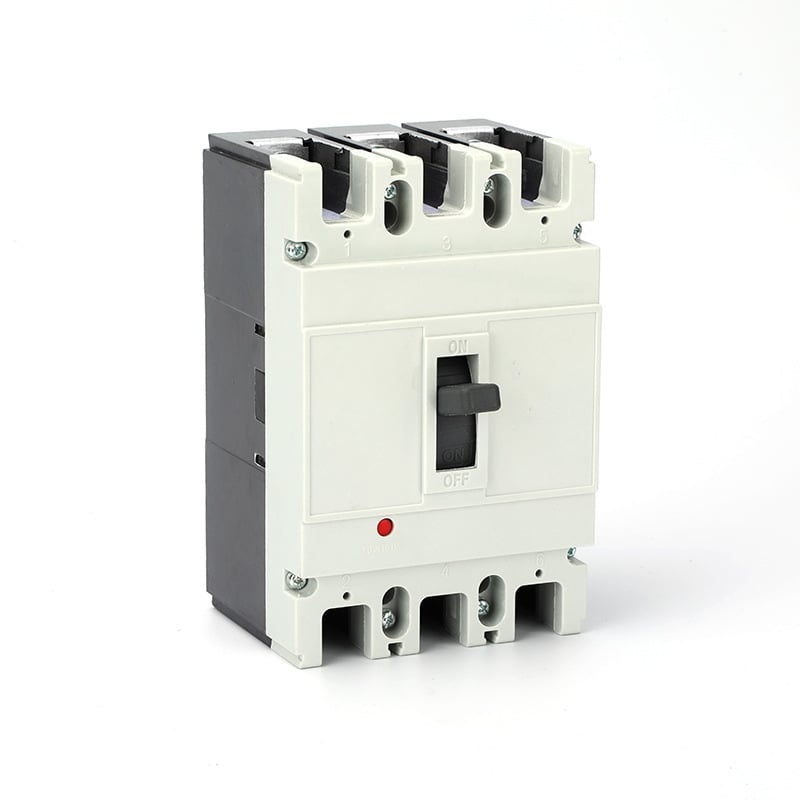
ZYM1L Molded case circuit breaker
Circuit breaker,Protection,Current,Installation

ZYM1L Molded case circuit breaker

ZYM1 Molded case circuit breaker
Breaker,Circuit,Protection,Installation

ZYM1 Molded case circuit breaker

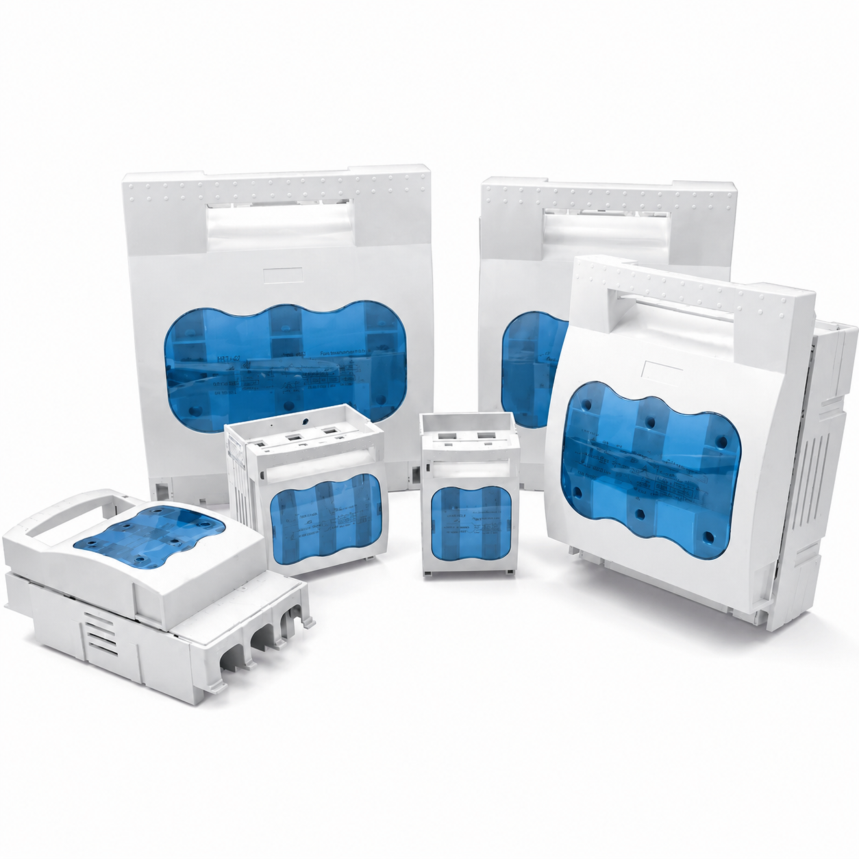
HR17 Fuse switch disconnector
Switch,Fuse,Isolation,Protection

HR17 Fuse switch disconnector

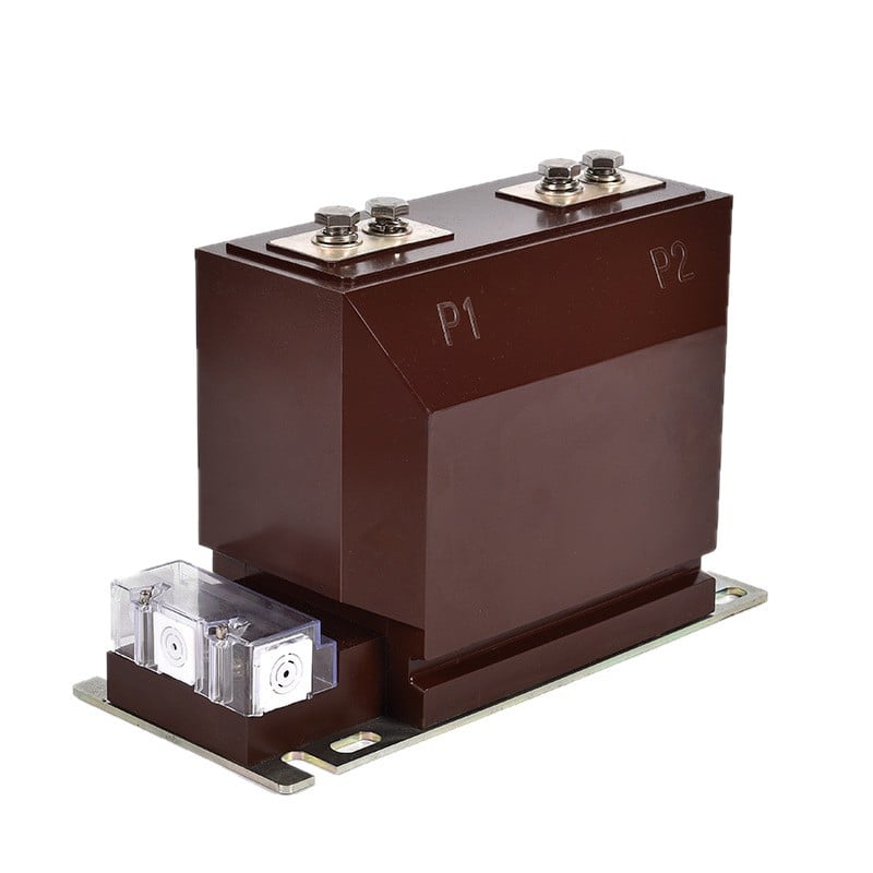
LZZBJ9-10N、H
Current Transformer,Measurement,Distribution,Insulation

LZZBJ9-10N、H

Get a Free Quote

Our representative will contact you soon.
Email
Mobile/WhatsApp
Name
Company Name
Message
0/1000
inquiry

Get a Free Quote

Our representative will contact you soon.
Email
Mobile/WhatsApp
Name
Company Name
Message
0/1000